Microcontroller Flexinol Driver
This article describes a microcontroller circuit to drive Flexinol muscle wires using a ULN2003A integrated circuit and a PIC 16F690. The method and circuit presented here provide a simple, low-cost solution with good flexibility well suited to the .004" and .005" Flexinol wires popular with students and hobbyists. It should hopefully be useful in a variety of robotic and other mechatronic projects.
Flexinol is a brand name for Nitinol nickel-titanium shape memory alloy (SMA) actuator wires. Also known by the brand name Muscle Wires, these small diameter wires can be made to contract with considerable force when activated with electricity or another source of heat. Although not as common as motors and other magnetic actuators, Flexinol has many potential applications for hobby robotics. For a general introduction to SMA actuator wires read Flexinol and other Nitinol Muscle Wires.
The PIC 16F690 used here as an example, is a good all-purpose controller from Microchip Technology's midrange offerings. It is a 20-pin 8-bit processor with flash-based memory and a number of enticing peripherial features including 12 analog channels, 3 timers, PWM, and I2C. It is the chip that ships with the PICkit2 starter kit and there is a good amount of sample source code around. Of course the basic interface described here could easily be adapted to any microcontroller platform - hobby controllers such as the Arduino, PICAXE, BASIC Stamp, or the MSP430 Value Line would all work nicely.
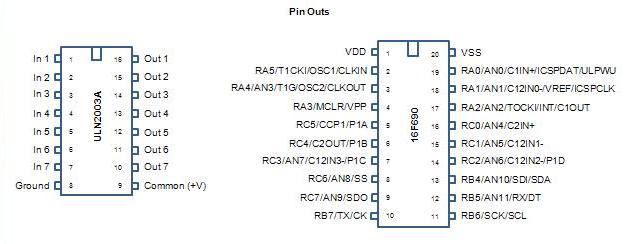
The ULN2003A is an array of 7 Darlington transistor pairs in a 16-pin DIP package. The IC includes not only the Darlington transistor pairs, but the necessary suppression diodes and current limiting resistors to create the full circuit. For many microcontroller applications (including this one) it is possible to drive loads by connecting outputs from the controller directly to inputs of the ULN2003A with no additional components required. Together with its other virtues, the ULN2003A is a tidy little chip. Each of its seven inputs on the left side of the chip connects to an output directly opposite on the right. In addition to the seven inputs and outputs, pin 8 is wired to ground, and pin 9 is optionally wired to positive voltage when sinking inductive loads. Pin outs for both the PIC 16F690 and ULN2003A are pictured below.
Each of the ULN2003A's outputs are rated for a maximum load of 500ma while the whole array can sink as much as a full amp depending on configuration and ambient temperature. When controlling multiple outputs simultaneously you must use the graph below, reproduced from the datasheet, to determine the maximum current available per output. The graph plots curves based on duty cycle, but for this basic circuit we will assume a 100% duty cycle and just use the far right of the curves. Therefore one simultaneous output will have a maximum current of 500ma, two outputs about 390ma each, three outputs about 300ma, etc. The .004" Flexinol needs about 200ma to achieve a 1 second contraction. Using the graph we could determine that up to five outputs could be sunk simultaneously at 200ma. However, it's best not to push quite that close to the maximum, so four outputs is a better working number. Remember that this restriction is for outputs conducting simultaneously. More than four outputs can be connected to 200ma loads, provided that they do not need to fire at the same time.

A schematic illustrating the basic Flexinol driver circuit appears below. As promised it is quite simple and hopefully for the most part self explanatory. The schematic shows four connections for clarity, but an actual application could have more or fewer, and could be tied to any available outputs on the PIC.

The values for the resistors will need to be calculated based on the supply voltage, the desired current, and the inherent electrical resistance of each run of Flexinol which will be of function of its length and gauge. (Ohm's Law refresher: resistance in ohms equals voltage in volts divided by current in amps (R=E/I)). When making this calculation the voltage drop across the ULN2003A must be accounted for. The drop is not a constant but will range dependent upon collector current as can be seen in the graph below, which as with the prior chart is reproduced from the datasheet. The graph shows both typical and maximum values for Vce.

As an example calculation, assume a 5 volt power supply and a two inch length of .004" Flexinol supplied with current of 200ma. Using the saturation graph above, the ULN2003A will drop about 1.1 volts at 200ma, so we can assume that roughly 3.9 volts is being delivered to the circuit. Plugging these values into R=E/I we get 3.9 V /0.2 A = 19.5 ohms resistance required. The .004" Flexinol has a resistance of 3.2 ohms per inch, which is 6.4 ohms in our two inch example. (The resistance and other characteristics of various gauges of Flexinol are provided in the overview article here). Subtracting 6.4 from the 19.5 total required leaves approximately 13.1 ohms to be made up in the circuit with resistors.
The sample code for the PIC is elementary and purely illustrative, cycling through the outputs 0-3 on PORT C which are shown connected in the schematic. The program uses delay loops and holds each pin high for about one second before advancing to the next state.
;--------------------------------------------------------------------------------- ; flexi-drive.asm ; ; sample code in Microchip Technology PIC Assembly Language ; to accompany a circuit that controls Flexinol actuator wire ; ; individual pins RC0-RC3 are brought high for intervals of approximately ; one second and the cycle repeats endlessly ;--------------------------------------------------------------------------------- ;--------------------------------------------------------------------------------- ; initialization - load the standard include file and set the configuration bits ;--------------------------------------------------------------------------------- list p=16F690 #include |
There are a few easy modifications that could be made to this circuit. If more outputs are needed, additional ULN2003As can be added, or if you need just one more the ULN2803A provides eight Darlingtons in an 18 pin package but is otherwise compatible. If you are considering substituting a ULN2003 or ULN2003L, first read the datasheets carefully as these chips have lower total power dissipation ratings. To sink higher currents than described here, outputs can be configured in parallel (doubled-up), however the per-chip maximums will still apply. For projects with significantly higher current requirements, consider using MOSFETs or even relays to manage the load.
About the Author: Ralph Heymsfeld is the founder and principal of Sully Station Solutions. His interests include artificial intelligence, machine learning, robotics and embedded systems. His writings on these on other diverse topics appear regularly here and across the Internet.
Other Articles You Might Find Enjoyable
Flexinol and other Nitinol Muscle Wires
Precision Flexinol Position Control Using Arduino
Design and Build Your Own Robot
First Look at the Texas Instruments LaunchPad
LaunchPad MSP430 Assembly Language Tutorial
Analog Sensors and the MSP430 Launchpad
Robot Obstacle Detection and Avoidance with the Devantech SRF05 Ultrasonic Range Finder
Introduction to the PICAXE Microcontroller
Setting Up A Differential Drive For Your PICAXE Project
Basic PICAXE Servo Interfacing